Defines parallel projection or perspective views by using a camera and target.
Note: Transparent ZOOM and PAN are not available in DVIEW. When you define a perspective view, ZOOM, PAN, transparent ZOOM and PAN are not available while that view is current.
The following prompts are displayed.
Specifies objects to use in the preview image as you change views. Selecting too many objects slows image dragging and updating.
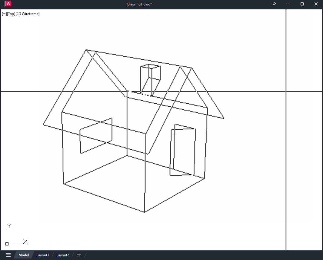
If you press Enter at the Select Objects prompt, DVIEWBLOCK displays a preview image. You can create your own DVIEWBLOCK block in a 1 unit by 1 unit by 1 unit area, with its origin at the lower-left corner. The following illustration shows an example of using the default DVIEWBLOCK to set the view (moving the graphics cursor adjusts the view).
Rolls the view under the camera. The point you select with your pointing device is a start point for the dragging operation. Your viewing direction changes about the target point as you move the pointing device.
The angles must be positive. The direction angle indicates the front of the view, and the magnitude angle determines how far the view rolls.
Specifies a new camera position by rotating the camera about the target point. Two angles determine the amount of rotation.
Sets the camera's position based on the specified point.
Enter Angle from the XY Plane
Sets the camera's position at an angle above or below the XY plane. An angle of 90 degrees looks down from above, and an angle of -90 looks up from below. A camera angle of 0 degrees places the camera parallel to the XY plane of the user coordinate system (UCS).
Toggle (Angle In)
Switches between two angle input modes. Entering an angle at the Command prompt locks the cursor movement so you see only the positions available for that angle. Toggle unlocks the cursor movement for the angle, and you can use the cursor to rotate the camera.
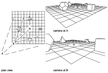
Enter Angle in XY Plane from X Axis
Sets the position at an angle in the XY plane relative to the X axis of the current UCS. This angle measures from -180 to 180 degrees. A rotation angle of 0 degrees looks down the X axis of the UCS toward the origin.
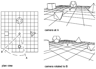
The illustration shows the camera rotating to the left from its initial position, leaving its angle from the XY plane unchanged.
Toggle (Angle From)
Switches between two angle input modes. Entering an angle at the Command prompt locks the cursor movement so you see only the positions available for that angle. Toggle unlocks the cursor movement for the angle, and you can use the cursor to rotate the camera.
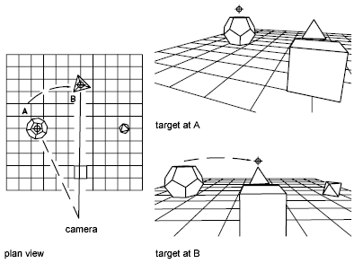
Specifies a new position for the target by rotating it around the camera. The effect is like turning your head to see different parts of the drawing from one vantage point. Two angles determine the amount of rotation.
Enter Angle from the XY Plane Enter Angle from the XY Plane Toggle (Angle In) Toggle (Angle In) Enter Angle in XY Plane from X Axis Enter Angle in XY Plane from X Axis
The illustration shows the effect of moving the target point from left to right, leaving its angle from the XY plane unchanged.
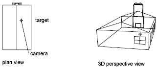
Moves the camera in or out along the line of sight relative to the target. This option turns on perspective viewing, which causes objects farther from the camera to appear smaller than those closer to the camera. A special perspective icon replaces the coordinate system icon. You are prompted for the new camera-to-target distance.
A slider bar along the top of the drawing area is labeled from 0x to 16x, with 1x representing the current distance. Moving the slider bar to the right increases the distance between camera and target. Moving it to the left decreases that distance. To turn off perspective viewing, click the Off option from the main DVIEW prompt.
If the target and camera points are close together, or if you specify a long-focal-length lens, you might see very little of your drawing when you specify a new distance. If you see little or none of your drawing, try the maximum scale value (16x) or enter a large distance. To magnify the drawing without turning perspective viewing on, use the Zoom option of DVIEW.
The illustration shows the effect of moving the camera along the line of sight relative to the target, where the field of view remains constant.
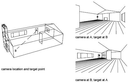
Locates the camera and target points using X,Y,Z coordinates. You can use XYZ point filters.
To help you define a new line of sight, a rubber-band line is drawn from the current camera position to the crosshairs. You are prompted for a new camera location.
A rubber-band line connects the target point to the crosshairs to help you place the camera relative to the target. The illustration shows the change in view as you swap the camera and target points. Lens and distance settings are the same in each case.
For information about entering direction and magnitude angles, see Point Specification.
Shifts the image without changing the level of magnification.
If perspective viewing is off, dynamically increases or decreases the apparent size of objects in the current viewport.
A slider bar along the top of the drawing area is labeled from 0x to 16x, with 1x representing the current scale. Moving the slider bar to the right increases the scale. Moving it to the left decreases the scale.
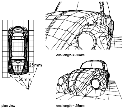
If perspective viewing is on, Zoom adjusts the camera lens length, which changes the field of view and causes more or less of the drawing to be visible at a given camera and target distance. The default lens length is 50mm, simulating what you'd see with a 35mm camera and a 50mm lens. Increasing the lens length is similar to switching to a telephoto lens. Decreasing the lens length widens the field of view, as with a wide-angle lens.
A slider bar along the top of the drawing area is labeled from 0x to 16x, with 1x representing the current lens length. Moving the slider bar to the right increases the lens length. Moving it to the left decreases the lens length.
Twists or tilts the view around the line of sight. The twist angle is measured counterclockwise, with 0 degrees to the right.
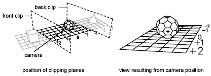
Clips the view, obscuring portions of the drawing that are behind or in front of the front clipping plane. The front and back clipping planes are invisible walls that you can position perpendicular to the line of sight between the camera and target.
Obscures objects located behind the back clipping plane.
Obscures objects located between the camera and the front clipping plane.
Turns off front and back clipping. If perspective viewing is on, front clipping remains on at the camera position.
Suppresses hidden lines on the selected objects to aid in visualization. Circles, solids, traces, regions, wide polyline segments, 3D faces, polygon meshes, and the extruded edges of objects with nonzero thickness are considered to be opaque surfaces that hide objects. This hidden line suppression is quicker than that performed by HIDE, but it can't be plotted.
Turns off perspective viewing. The Distance option turns on perspective viewing.
Reverses the effects of the last DVIEW action. You can undo multiple DVIEW operations.